|
|
|
To Katya
PROJECT
REAL TIME OPERATING SYSTEM BASED ON ACTIVE OBJECT
1. Annotation
A challenge of this project is a creating of pure object-oriented small footprint real-time operating system (RTOS) for embedded devices. C++ language, Active Object (AO) and hierarchical state machine (HSM) design templates are chosen as implementation bases. Using of message driven synchronization of Active Object allows refusing any other synchronization mechanisms. It is making developing of embedded application easy, improves response time, eliminates priority inversion problem, dismisses thread blocking and increase stability of RTOS.
2. Project goals
2.1. Using pure Object Oriented Approach
Object oriented approach (OOA) allows encapsulate data in address space of objects. AO expanses idea of data encapsulation in time domain. OOA makes easier developing of embedded systems and allows using UML design tools for automation of embedded software developing.
2.2. Multitasking with message synchronizing
Avoid semaphore, blocking of threads and priority inversion. Using only AO message mechanism.
3. Introduction
3.1. Design of the system: Object Oriented Approach and message driven synchronized multitasking
Design of described RTOS is based on object oriented approach. Why so important to use a pure OOA? OOA itself is not a technology or instrument but using one can directly improves characteristics of designed system. On the contrary, OO compilers produce a larger and slower code than non-OO ones. But OOA is a methodology that allows to developer who uses it to make a systems substantially reliable and scalable, allows using analysis and synthesis theory's methods.
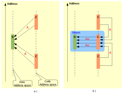
Fig. 3.1. Unlimited way to access data (a) allows any piece of code reads/writes data of any area of address space but OO approach (b) allows only object's code to manipulate with own private data.
The key problem of multitasking RTOS is problem of data protection or how avoid an undesirable access to data. OO approach gives a good conception of data protection - this is a data encapsulation inside object. Data of given object can be read and modified only by methods of class that owns the object. Other objects of given class and an objects of another classes are forbidden to directly access the inner data of the object. This situation guarantees that given data can be accessed only from well defined and limited piece of code (methods of given class). Let's take a look at Fig. 3.1.(b). This diagram shows a permitted ways to access object data. So data in address space is protected from unauthorized access with using OOA. But this is not true when we consider data protection in time domain (in time base).
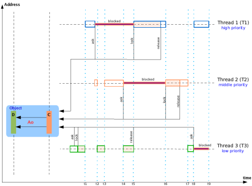
Fig. 3.2. Synchronization of concurrent processes using the same resource (object with data)
When RTOS executes a multitasking application then a different threads of the application try to concurrently access the same data (or invokes the same method of different objects that is equivalent). This situation can lead to unpredictable changes and destroying of data. In order to regulate it the data processing by one thread has to be blocked for accessing of other threads. Concurrent access to data can be prevented by synchronization mechanism such as semaphore or mutex [1]. Lets look at Fig. 3.2. Here is three threads are running and are trying access data of the same object. When thread 3 asks for data and gets an access to one by invoking of some object's method then thread 3 have to lock the object's data (to prevent access from others ones - T1 and T2). Then thread 1 try to access the data but the object's semaphore does not allow the operation. So T1 (high priority thread) have to wait for T3 (low priority ) while it releases this resource. Faremore slice time (t3-t4) that can be used by high priority thread 3 now is used by middle priority thread 2 so priority inversion occurs in this period. Attempt to fix up this behavior by using of more complex semaphores and mutexes leads to complexity of software and to degradation of system's reliability. If OOA gives us a hard data protection in address space may be one can do the same things in time? Active Object design pattern that widely using in other software areas [2] can do it.
3.2. Using Active object design template
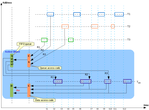
Active Object (see Fig. 3.3.) consists of data object itself (D and C), inner own thread (Tao) and FIFO (first input first output) queue (Q) for keeping of incoming messages (R1, R2, R3). When other thread (T1, T2 or T3) wants to access data this thread put request to AO queue instead of direct calling of an object's method. The inner AO thread (Tao) is running in loop and is checking the queue for unprocessed request and then invokes needed object's method. The all requests from different threads are sequentially processed and situation when one thread is blocking other is impossible. The main idea of the project is a building of RTOS as a container of Active Objects which are running independently and are exchanging of messages between them. The only entity of this RTOS is Active object and the fact tremendously simplifies design and synchronization mechanism of the system.
Fig 3.3. Concurrent processes with AO
4. AO RTOS kernel model
4.1. Base components and message exchanging
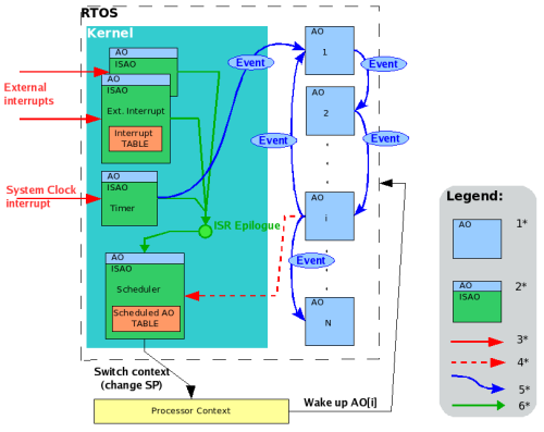
Fig 4.1. Component diagram of real-time operating system based on Active Object Pattern. 1* - Active Object (AO), 2* - AO for interrupt service, 3* - external (asynchronous) interrupt, 4* - program (synchronous interrupt), 5* - tracks of events (messages) between AO, 6* - return after interrupt service.
There are two generic types of object in AO RTOS, this is active object (AO) and active object for interrupt processing (ISAO) that is subclass of AO. AO can receive and send messages to any other AO and ISAO. ISAO can moreover receive and process external and internal (programming) interrupts. There are two ISAO those are necessary for kernel work, ones are Timer and Scheduler ISAO's. After processing interrupt Timer executes epilogue code (as any other ISAO) and transfers control to Scheduler that switches processor context to AO with highest priority. The Timer ISAO receives and processes interrupts from system clock (or other timing service) as shown on Fig. 4.1.
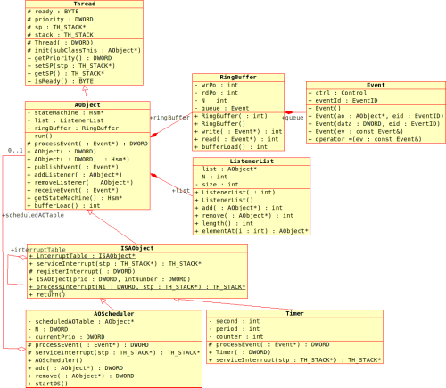
Fig 4.2. Kernel class diagram
A super class of the AORTOS class hierarchy is Thread that supports of processor context switching or multithreading in other words. An AObject is a direct subclass of Thread and encapsulates a data and functionality for active object control. A RingBuffer and ListenerList classes help to uphold a functioning of AObject. A custom active objects have to subclass this class. Next class in the hierarchy is ISAObject that subclasses AObject. The ISAObject defines interrupt processing service. This class is a super class for Timer and Scheduler those control the running of RTOS. Other custom objects for external interrupt serving have to subclass one. Now take a look more close to these classes.
4.2. Thread class
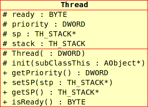
Thread class (Fig 4.3.) is responsible for keeping AO thread context while active object is not active. It contains a few fields:
Fig. 4.3. Thread class diagram
This class has a few methods but only one
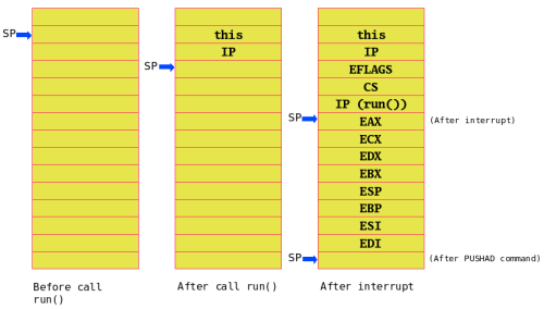
init() requires explanation. The goal of the method is preparing of AO for start up or in other words we have to simulate usual inactive state of AO so after activation by RTOS scheduler it can properly run. In active state AO executes method run() and after interruption become inactive. So in inactive state AO stack includes trace of run() call and interrupt trace (about the RTOS interruption mechanism see below) as showed in Fig. 4.4. First init() puts in stack value of object's this then puts return address from run() (it is fictive, because AO does not going return from run()). After that it puts CPU FLAGS = 0x00000202, value CS register and value IP register equals start address of run() method. init() prepares stack for RTI command. For POPA command it includes in stack values of CPU registers as showed in Fig. 4.4. Fig. 4.4. Stack explanation
4.3. Active Object (AObject) class
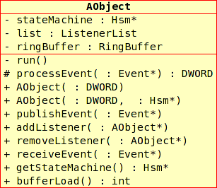
AObject class is main class of the architecture. The all objects of RTOS are a subclasses of the class.
Fig 4.5. Active Object class diagram
AObject has a following fields:
Methods of AObject:
4.3.1. Helper class RingBuffer
4.3.2. Helper class ListenerList
4.4. Interrupt service Active Object (ISAObject) class
ISAObject is subclass for all AO that are going to process of interrupt. The each interrupt makes execute Interrupt Service Routine (ISR) that is written in Assembler (see porting RTOS below). The ISR save CPU context and invoke static method of ISAObject
processInterrupt( DWORD iN, TH_STACK * stk ) and passes two parameters: iN - interrupt number (corresponds to CPU interrupt descriptor table (IDT)); stk - pointer to current stack. After an interrupt has been served RTOS scheduler gets control to decide what Active object have to become active depend on them priority and ready state. Fig 4.6. ISAObject class diagram
Fields :
There are a few notes about
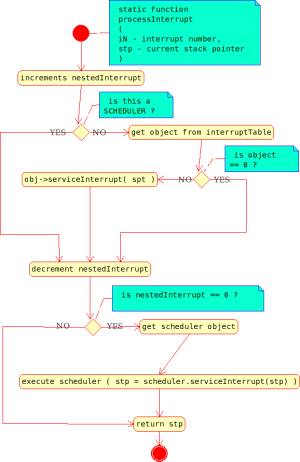
processInterrupt() code. Execution of the function starts with increment of nestedInterrupt variable. The all nested interrupts will be processed but its do not activate a scheduler. Scheduler is invoked during an epilog of first interrupt processing. Fig 4.7. Flow of interrupt processing
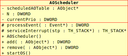
4.5. Scheduler class for multitask control
Scheduler object can be activated in two way:
Fig 4.8. Scheduler class diagram
Fields:
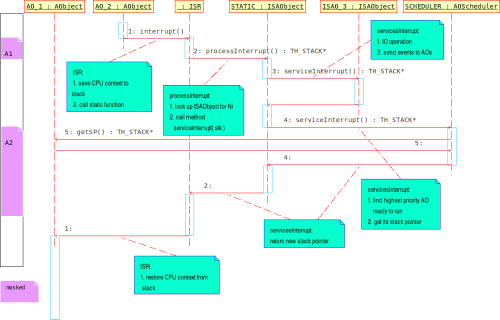
Fig 4.9. Flow of program interrupt processing by Scheduler
Active objects added to the RTOS scheduler have to have unique priority number from range 0 - (TH_SCHEDULED_LIST_LENGTH-2). Scheduler has priority (TH_SCHEDULED_LIST_LENGTH-1). Starting of RTOS has a few steps:
4.6. Timer class as a simple interrupt service AO
RTOS has to have at least two ISAO Scheduler and Timer. Timer is a heart of system it makes the scheduler to find high priority AO that is ready to run.
5. Hierarchical State Machine design model.
The design of HSM in C++ is close to design of Java HSM. See detailed explanation here and in code comments.
6. Implementation
The project is implemented under Linux using GCC and Eclipse IDE with CDT plugin. The project is building by ANT.
6.1. Project folders description
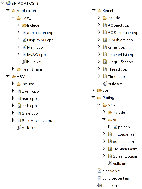
Eclipse's Project folder consist of follows:
Fig 6.1. Eclipse project folders
Sub folders looks like sub-projects and contains source code and ANT script file build.xml for compiling this code:
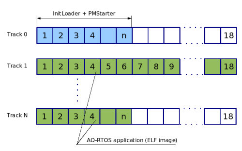
The result of building of project is a bootable floppy disk with real-time application. Then produced floppy disk is used to boot and run embedded application on Intel-x86 PC target - just put the floppy-disk to drive and push 'reset' button (of course you have to set PC BIOS to start to boot from floppy).
6.2. Ix86 port (assembler)
Porting to Ix86 target is provided by assembly code modules that is contained in follows files:
Fig 6.2. Floppy disk map
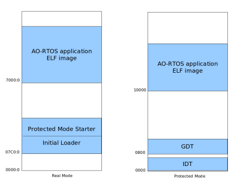
Fig 6.3. Memory map : real and protected modes
Start up process has a few steps :
6.3. Ant Make procedure
Project building starts with running of ANT script
build.xml from root folder of project. The build script uses build.properties file as a input arguments:
The main build.xml script has a three targets:
init, prepare - prepare build space. compile - the target run other ant build scripts for sub-projects: Kernel, Porting, HSM and application itself. link - the target collects and links compiled object files from above target and makes binary file. floppy - makes a floppy disk for booting and deploying the application on target PC.Build scripts in sub-folders Kernel, HSM and Application/... make compilation tasks using GCC compiler g++. Porting/Ix86 folder contains script for compiling source files using assembly compiler NASM.
7. Simple examples
7.1. Test 1
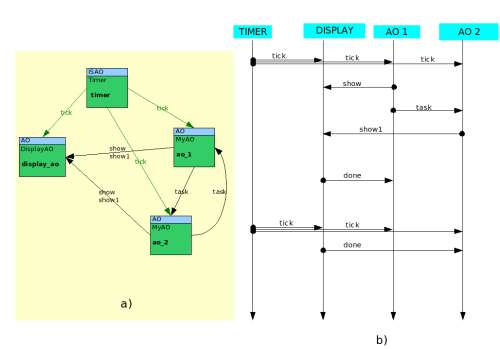
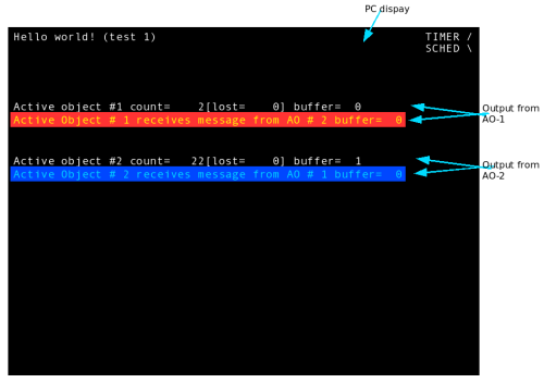
The application defines two classes DisplayAO and MyAO. Both are an Active object subclasses. The task implements a simple exchange of messages between three Active object : AO_1, AO_2 and display.
DisplayAO is a wrapper for
Display object (Display class is defined in Porting/Ix86/pc/pc.cpp). DisplayAO is waiting for messages (or events) with ID = 'show' or 'show1' or 'tick'. If 'show*' message comes then DisplayAO retrieves the message from ring buffer, extracts from the message a reference to AO that sent this one. Then it gets a string from the AO and displays the string. And finally sends to the AO message 'done' to notify the AO that operation is over. 'tick' message is used to clean a display after delay.Fig. 7.1. Message exchange : component activity diagram (a) shows paths of event exchange, sequence diagram (b) shows how components are acting in time
MyAO is a custom active object that waiting for messages 'tick', 'task' or 'done'. After MyAO gets 'tick' message from
Timer counts it and selects one second moment for sending information message to DisplayAO. MyAO sends each max seconds message to other AOs. If the AO receives 'task' message from other AO then it publishes message 'show' for DisplayAO.Fig 7.2. Screen of PC display with running Test_1 application.
7.2. Test 2
Description coming soon. See code for details.
8. Download
Download source code
9. Conclusion
10. References
[1] Jean J. Labrosse. 2002. MicroC/OS-II, The Real-Time Kernel. CMP Books, ISBN: 1-57820-103-9
[2] Miro Samek, Ph.D. 2002. Practical Statecharts in C/C++. Quantum Programming for Embedded Systems. CMP Books, ISBN: 1-57820-110-1
1 November 2006
|

 H O M E P A G E
A L E X E I K R A S N O P O L S K I


